Technical Design
The original P2P proposal called for indoor installation,
with a distance of only 25 metres (75') between the switch panel and
the marquee. The technical design for this indoor installation was relatively
simple, if repetitive: each switch would be wired in series
with the corresponding light bulb, switching the 120 volt supply directly.
The curatorial committee of CAFKA.02, for which the piece was
created, preferred to showcase the piece in Civic Square, in
front of City Hall. This outdoor installation meant that P2P had
to be completely redesigned, while maintaining the functional simplicity
which makes the piece so compelling. The outdoor installation
imposed two main constraints:
-
Artistically, it was important that the piece use common
household light switches. These switches are not waterproof, and the
outdoor installation meant that performance may
degrade if the switches rusted over the course of the exhibit. In
addition, it was out of the question to have these switches switching
120 volts outdoors, out of concern for the safety of participants
who may use the piece in the rain.
-
The other main constraint was the distance between the switch
panel and the marquee: 150 metres (450') of cable would be required to
make one run from the switch panel to the marquee. This meant nearly
20 kilometers (12mi) of cable, in order to direct-wire switches to bulbs.
Aside from the cost, it was simply impractical; another way had to
be found.
The solution to the safety concerns was to confine high voltages to
the marquee and the relay box, which the public did not have direct
access to. This left the possibility that some switches might need
to be replaced if it rained too much. We did have to shake out a
couple of switches after a particularly long, hard day of rain.
In order to reduce the amount of cabling between the switch panel
and the relay box, a 128-bit serial latch was designed from eight
16-bit latches (Fairchild 74F676). The switch
outputs are all latched in parallel, and that data is shifted serially
along a CAT5 cable to a decoder circuit in the relay box, 500 feet
away. The decoder circuit is essentially the opposite: a 128-bit
serial-input parallel-output register was constructed from sixteen
8-bit latching relay driver chips (Allegro Micro UCN5841/5842). Each
of the outputs drives a relay on a modified RIB101 relay interface board
(BSoft Software, Inc), which turns the corresponding lamp on or off.
A single microcontroller (MicroChip PIC16F84A) provides the timing, clocking
the serial data line at 50kHz, meaning the whole display is refreshed
roughly 400 times per second. RS422 drivers (Maxim MAX3043/3095) were
used to transmit data and clock differentially along the CAT5 cable.
Two unused wires in the CAT5 were used to bring power back from the relay
box to the switch panel electronics, meaning the only thing leaving the
switch panel is the CAT5 cable.
Suprisingly few people asked how it actually worked. Part of
our goal was to make the interface design easily-understood and accessible
to all. The workings are actually quite complicated, but it was done in
such a way that people were not surprised at being able to control 125
bulbs from so far away. Or maybe they just didn't think about it. Either
way, the interface design was a success, from our point of view, but we
were still surprised that more people didn't ask how it worked.
Installation Requirements
The final P2P design is made up of four components:
the Marquee, the Relay Circuits (which switch the power to the bulbs),
the Switch Panel, and the Switch Panel Electronics (which reads the
switch values and transmits to the Relay Circuits).
|
|
|
|
| Marquee
| Relay Circuits
| Switch Panel
| Switch Panel Electronics
|
Several aspects of the installation are site-specific. Please see the images
above for details of the local installation requirements described below. Images
will open in a seperate window.
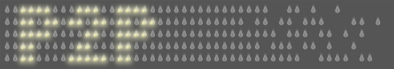
- Marquee
-
- A frame at least 2x8 metres (6'x24')
This is constructed locally mainly because it is relatively easy to build and
very hard to transport. Once constructed, the frame is covered in black
Textilene, a wind-permeable fabric, and airline cable is strung to which
the bulbs will be affixed.
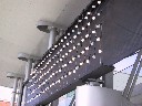
- A support structure for the frame
The complexity of
this requirement depends on what can be used locally: it can be hung on the
solid wall of a building, or on pillars or other supports as it was in these
images. The bulbs are installed after the frame has been hung.
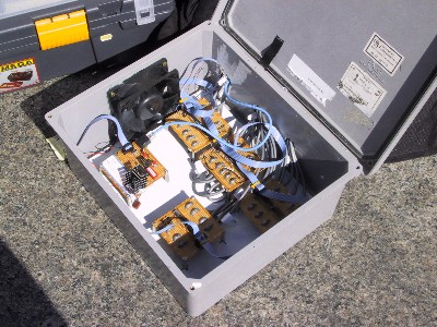
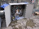
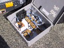
- Relay Circuits
-
- 60A @ 110VAC (ideally in 6 sockets)
The relays are divided into five 25-relay control boards. Each relay operates
one 50W light bulb. In addition to the bulb power, each relay control board
requires ~1.5A @ 5VDC, and the decoder electronics which drives the relays
requires approximately another 1A. The relays are rated up to 250VAC, but
unfortunately the special bulbs we use in the piece are only rated to 130V.
- A housing of some kind
The type of housing required will depend if the relay circuits will be located
outside or inside. This is site-specific and hard to transport, so needs
to be sourced locally.
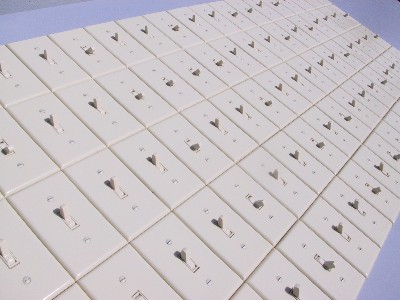
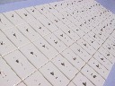
- Switch Panel
-
- location
The switch panel is housed in a structure which is ~1 metre (36") high and has a
footprint of approximately 70x310 centimetres (27"x10').
- CAT5, 8-conductor cable
A length of 8-conductor CAT5 cable sufficiently long to connect the switch panel
to the relay circuits. Since we are not communicating at Ethernet data rates,
repeaters are not required beyond the regular limit of 100 metres (300'). Previous
installations have been successful with 500' of cable without a repeater.
- Switch Panel Electronics
-
- no local needs
Power for the electronics arrives from the relay circuit box via two of the CAT5
wires.
Other Technical Information
Aside from installation requirements, the following technical information may be
of interest.
- The switch panel uses low voltage (5VDC) only, and this power comes down the
CAT5 cable from the relay box. Thus, potentially dangerous higher voltages are
confined to the marquee and relay box, which can be safely located out of reach
of the public.
- We use special silicon-coated rough-service bulbs, which are designed especially
for the low-frequency high-amplitude vibrations they may see from wind. Each
bulb is affixed to airline cable using nylon cable ties, meaning it is nearly impossible
for them to come into contact with anything which could break them. In the unlikely
event that one does break, the silicon coating means they do not shatter; no glass can
fall from the marquee.
- P2P was exhibited for ten days in Kitchener, Canada, in September 2002. Over
those ten days, it was not vandalized once.
- At that exhibit, the bulbs were subject to relatively high
winds, up under the canopy of City Hall, but none broke. We did
have to replace three bulbs which burned out early, likely due to manufacturing defects.
- In Kitchener, it rained hard for one whole day. Other than having to shake the
water out of a couple of the switches, the piece remained fully functional.
Home
-
Images
-
Technical
-
Press
-
Exhibits
-
Artists
-
Contact